FaCT
About FaCT | Adapative Imaging | Controlled Dose Imaging | FaCT Photos | FaCT Images
FaCT: FastSPECT II and CT
FaCT is two small-animal imaging systems in one. It consists of a SPECT imager, FastSPECT II, and a new adaptive small-animal x-ray CT system. Each system is capable of operating in a stand-alone mode, but the two systems can be combined into a single, dual-modality system that does SPECT/CT. Use the links at the top of this page to learn more about FaCT and adaptive imaging.
About FaCT
FaCT stands for FastSPECT II and CT. FastSPECT II (PowerPoint file) is an existing small-animal SPECT imager. The CT system is a brand new, custom built helical-scan cone-beam CT system for small-animals.
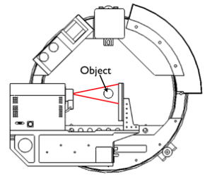
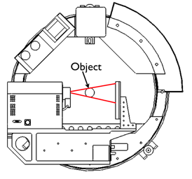
The new CT system possesses several unique features to facilitate the exploration of adaptive imaging procedures. It can adjust its magnification and also adjust its cone of illumination. These two features allow the CT system to perform high-magnification, region-of-interest studies at low dose.
Fast reconstruction and adaptive algorithms require a substantial amount of computing power. To meet these needs, FaCT possesses the current state-of-the-art in graphics processing units (GPUs) for handling massively parallel computation tasks and on-the-fly reconstruction.
The Center for Gamma-Ray Imaging uses FaCT to explore adaptive imaging procedures and how they might improve performance on a wide variety of medical tasks.
Basic CT Specs
- 130 kV source with 6 micron diameter focal spot
- 2040 x 1024 pixel CMOS detector with 48 micron pixels
- Capable of helical or circular scan geometries, and cone- or fan-beam emission profiles
CT Adaptive Features
- Adjustable magnification from roughly 1x to 10x, depending on object size.
- Adjustable aperture for selecting desired section of x-ray beam to illuminate object.
- Adjustable x-ray tube voltage and current.
Links for further reading
A Task-Based Approach to Adaptive and Multimodality Imaging
Adapative Imaging
The idea behind adaptive imaging for medical imaging is that the system should autonomously change its configuration to best match the object being imaged. But what is meant by ìbest?î How does one decide what the best image or best imaging system is?
If we are to achieve any sort of scientific rigor in our analysis of images and imaging systems, we must define a task for which the image is to be used, and then judge the quality of that image (or set of images) by how well that image helps an observer perform that task. (See Image Quality)
Examples of tasks we might wish to perform with images taken by a medical imaging system include: tumor detection, estimation of left ventricular ejection fraction, and estimation of a tumorís location. An observer can be a person, like a radiologist, or even a computer.
In adaptive imaging, as we currently envision it, an imaging system performs a quick scout scan of the object, analyzes the collected data from the object (quickly as well), and then adjusts its parameters (with knowledge of what the task is) for a second scientific scan to best help the observer perform the given task.
Our early research into adaptive imaging indicates that imaging systems that can adjust their imaging parameters according to the object being imaged can greatly increase their performance on various tasks. The new CT part of FaCT will help us to explore more thoroughly the benefits of adaptive imaging procedures.
Low-Magnification Position
High-Magnification Position
Controlled Dose Imaging
“Adaptive CT for High-Resolution, Controlled-Dose, Region-of-Interest Imaging”
In this adaptive procedure, we use a quick preliminary scan of the object to determine a region of interest within the object, and then use that information to direct the full diagnostic scan. The procedure is explained in the images and captions below. Scan explanation below.
FaCT Photos

CT system under construction
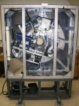
The CT system with back shielding panel removed
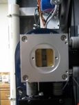
Beam-masking aperture installed on front of x-ray source. Provides ability to do both cone-beam and fan-beam scans
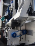
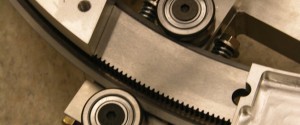
Drive system for adjusting magnification

Micro-stepped, high-torque stepper motor for precision gantry rotation

Leaded glass shielding for covering the rear port when the CT system is used in stand-alone mode

Detail of interlocks. The entire chamber is interlocked to ensure safe operation
 The 2 blue columns on either side of the entry port form an infrared ëlight curtainí that detects foreign objects entering the chamber and shuts down the x-ray source

One of the display panels indicating the status of the interlocks and whether or not x-rays are being emitted

Emergency kill-switch on the front panel ensures total safety
FaCT Images
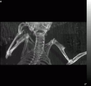
Mouse midsection reconstructed at 100 micron resolution, 1.4X mag
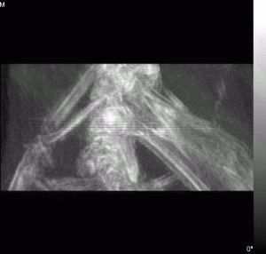
Same mouse reconstructed at 40 micron resolution
Please note that image sequences have been compressed for optimal web delivery and are degraded from the original quality.

