Project Workspace Introduction
Important Demo
To learn about the workspace, it is recommended that new users have fun with the Simple Disk Tutorial. This tutorial uses the concepts which are discussed below.
Main Project Workspace
This document describes the various features of the Main Project Workspace:
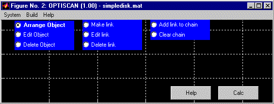
The name of the OPTISCAN system, in this case simpledisk.mat, is placed in the window’s titlebar.
System Menu

- Save: Allows the user to “save” the current system to disk. Many of the OPTISCAN model’s data are stored in separate files. These are saved immediately. For example, if the source’s electric fields are modified using the “Add A Piece” wizard, then they are immediately saved. The source’s dimensions are not saved until the system is saved.
- Save As: Allows the user to save the current system to a new a project. The entire project is copied to the new project folder.
- Preferences: Allows the user to set global sampling parameters and other values.
- Close: Closes the current system. The user is asked if the current system should be saved before the Project Window is closed.
Build Menu
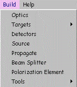
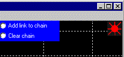
The “Build Menu” allows the user to create physical optics objects. If the “Source” item was chosen from the “Build menu,” then OPTISCAN creates a new source and places it in the upper-righthand-corner of the project workspace:
The various items that can be created are described in the Optiscan Cheatsheet.
Accessories Menu
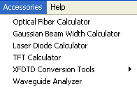
- Optical Fiber Calculator
- Gaussian Beam Width Calculator
- Laser Diode Calculator
- XFDTD Conversion Tools:
- Convert XFDTD to Optiscan
- Field Map Generator
- Waveguide Analyzer
Object Controls

- When “Arrange Object” is actived (clicked on), then objects may be relocated in the project workspace by dragging them around with the mouse.
- When “Edit Object” is actived (clicked on), the objects in the project workspace may be editted by clicking on them.
- When “Delete Object” is activated (clicked on), the objects in the project workspace may be deleted by clicking on them.
It may be more convienient to right click an object in the project workspace and then choose the desired action from the menu which is displayed:

Links are used to specify how electric fields propagate through an OPTISCAN model. The following model shows the electric fields propgating from a source to a reflective target to a plot:
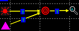

- When “Make Link” is activated (clicked on), links can be created by clicking on the object, which is the source on the electric field, and then clicking on the object which the electric field is being propagated to.
- When “Edit Link” is activated (clicked on), the properties of a link can be displayed for modification by clicking on it. The following image shows what happens when a link’s type is changed:

- When “Delete Link” is activated (clicked on), the links in the project workspace can be deleted by clicking on them.
An OPTISCAN link shows how an electric field propagates from one optics object to the next. A chain specifies the order in which the links are evalulated. In the following system:![]()

The link labeled “0:1” is evaluted first, the link labeled “T:2” is evaluated second, and the link labeled “R:3” is evaluated last.
Help Button
![]()
brings up a Web Browser to display the OPTISCAN Help Desk.
Calc Button
![]()
initiates a simulation by displaying the System Preferences Dialog.

