Tutorial: Simulating a Rotating Disk
- Create an Optiscan Project Folder
- Start Optiscan
- Choose the Name for Your Project
- Create the Objects You Need
- Create Links
- Saving the System
- Modify Link Attributes
- Modify the Link Attributes of the Delta/Target Link
- Configure the Delta Object
- Set the Size of the Source
- Configure the Target
- Building the Chain
- Simulate the Model
Create an Optiscan Project Folder
Create a new folder on your computer for Optiscan projects. The folder “MyProject” should not already exist in this folder.
Start Optiscan
At the MATLAB command line use the startup command. You must be in the Optiscan installation directory for this to work. The Optiscan Project Wizard should be displayed.
Step 1: Select New Optiscan Project – ![]()
Step 2: Click the Next Button – ![]()
Choose the Name for your Project
Step 1: Enter the Name of Your Project
- Name the Project “MyProject”
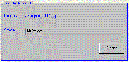
Step 2: Click the Next Button to Create the Project.
- You should see the Project Window.
Create the Objects You Need
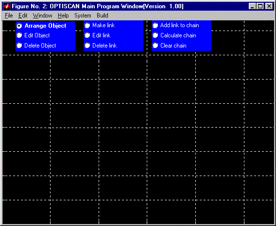
Step 1: Objects are created by using the Build menu.
- They are always placed in the upper right hand corner of the Project Window.
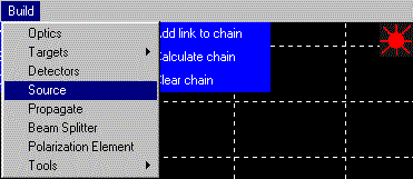
Step 2: Move your new object by dragging it to the desired location.
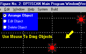
Step 3: Create some objects and position them like the picture.
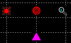
Sub Step | Use Build Menu Item | Icon
- Create A Delta | Build:Tools:Gooey Delta |

- Create a Look | Build:Tools:Look |

- Create a Target | Build:Targets:Reflective Target |

- Delta Object – Will be used to simulate disk movement.
- Look Object – Displays/Plots results.
- Reflective Target – Normal reflective Target.
Create Some Links
Step 1: Click on the Make Link radio button in the Project Window.

Step 2: Click on the Source and then the Target.
- The first object that is clicked is augmented with a selection box.
- After the Target is clicked on, the Link is constructed and the Source’s selection box is removed.
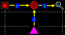
- The T on the link stands for “Transmitted.” This denotes that the link passes transmitted electric fields.
![]()
Step 3: Create the rest of the models links, as shown on the right.
- The arrows denote the flow of light through the Optical System.
Saving the System
Step 1: Feel free to save the system at any time throughout the tutorial.
- The system file contains the parameters of each object and their layout.
- The masks, scripts, and I/O data are permanently stored in the project’s various folders.

Modify Link Attributes
Step 1 – Click on the Edit link radio button in the Project Window.

Step 2 – Click on the Link between the Target and Look.
- The Link Properties editor should be displayed.
See: Link Properties.
Step 3 Modify the Link Type to Reflected Fields.
- This is done because light is reflected of the target, and we wish to look at these reflected electric fields.
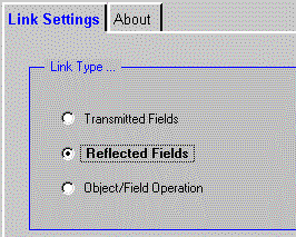
Step 4 Modify the Delta/Target link type to “Object/Field Operation” since the Delta object will modify the target’s window parameters.
Step 5 – The links should look like the ones here
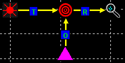
Modify The Link Attributes of the Delta/Target Link
Step 1 – Click on the Link between the Delta and Target
- The Link Properties editor should be displayed.
See: Link Properties.
Step 2 – Change the Link Type to Object/Field Operation.
- A link from a Delta to another object is always pointed at the other object.
The link type is typically set to Object/Field Operation so that the simulator knows that it only has to update the parameters of the object. This tells the simulator to only evaluate the Delta object, but not the Target Object. This may sound confusing, but without this type of link, the Target would be evaluated twice. Once for the Source/Target link and a second time for the Delta/Target link.
Configure the Delta Object
Step 1 – Click on the Edit object radio button in the Project Window.

Step 2 – Click on the Delta Object. The Variable Tool Panel should be displayed.
Step 3 Click on ![]()
Select “X Win Center” from the dialog box that appears, and then click OK. 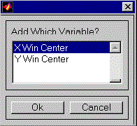
Step 4 Configure the “X Win Center” parameters as shown. Use These Settings for “X Win Center”:
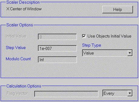
Step 5 Accept the changes by clicking ![]()
Set the Size of the Source
Step 1 Edit The Source
Step 2 Choose “Properties” from the Menu Items, and the click Go. 
Step 3 Modify the source’s dimensions and offsets to match those shown.
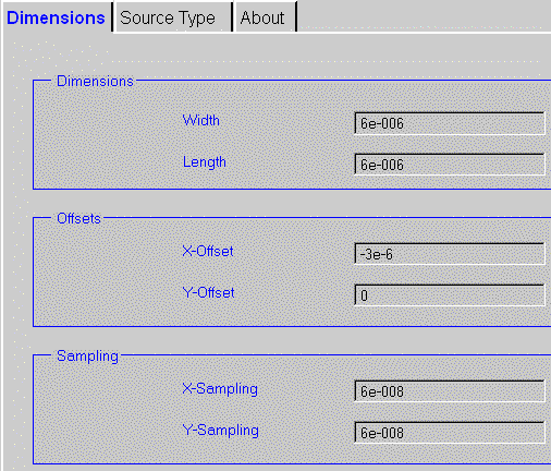
- Typically, the x-offset is equal to: -width/2
- This values will center the source on both the X and Y axes.
Configuring the Target
Step 1 Edit The Target
Step 2 Choose “Add Piece” from the Menu Items, and the click Go. 
Step 3 The first step is to tell optiscan where the “piece” mask is located. You can use the file: “Circle3.BMP” which comes with Optiscan.
- Click Next after you have specified this file.
- In the “proj” folder of the Optiscan distribution, there is a file called: “Circle3.BMP.” (black donut on white background)
Step 4 Click on the Full Win button. The green border shows you the “window” where the piece will be inserted. When you click on “Full Win”, the piece you are adding (circle3.bmp) will consume the entire area of the target.
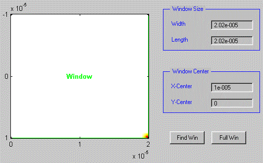
- You can specify a custom piece width and length, as well a custom piece x-center and y-center.
- Click Next after you have specified this window.
Step 5 The Bitmap scaling factor is specified to convert the BMP which is in RGB (red-green-blue) space to the scaling you desire.

- For this exercise, set the scaling to 0 for the minimum and 1 for the maximum.
- If a complex value is specified, then there is a phase factor introduced!
Step 6 The last step to adding a piece is to save the updated mask.
- Click on “Finish” to create the new mask.
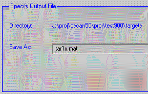
Step 7
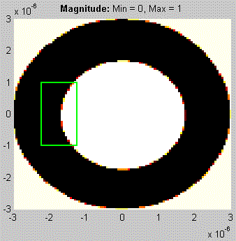
The result of adding the donut piece to the target:
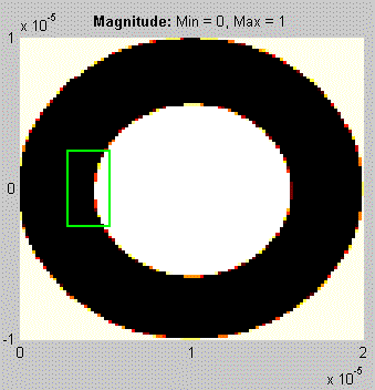
- The green box, on the left, is called the target’s window.
- The target’s window specifies the active portion of the target.
- By moving the target’s window to the right during the simulation, disk motion can be simulated.
Use the target’s “Properties” menu item to modify both the target’s dimensions and the target’s offsets to match the sources:
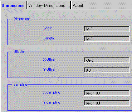
Set the Target’s window to the following dimensions.
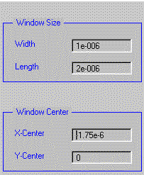
- see: Window Dimensions
Click on “OK” to close the “Target Properties.”
The result of changing the dimensions and window dimensions:
Building the Chain
Step 1 Click on Add link to chain. 
Step 2 Click on the Delta/Target link. The result of adding the delta/target link to the chain:
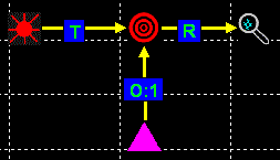
The label 1 indicates that this is the first step of the simulation.
Step 3 Add the Source/Target link to the chain.
Step 4 Add the Target/Look link to the chain. This should be the final result after all the links are added to the chain:
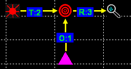
The meaning of this is that the Delta/Target calculation is performed; next, the Source/Target calculation is performed; and finally, the Target/Look calculation is performed.
In English: the Delta object positions the target’s window; light is shined onto the target; and finally, the look object produces an output plot.
The next section, Simulating The Model, sets the simulation parameter “Chain Count” to 5. This means that the model’s calculations are repeated 5 times. The difference of each chain calculation is the position of the window.
Simulating the Model
Step 1 Click the “Calculate Chain” button to start the calculation.

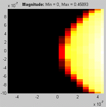
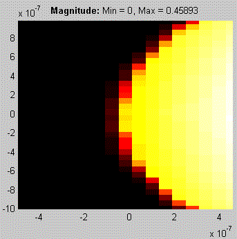
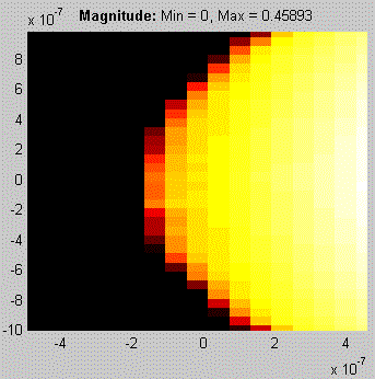
Step 2 Set the “Chain Count” to 4. This will generate four calculations of the reflection of the source off the target.

Click the OK button to begin the simulation.
Step 3 You can watch the system as it is calculated. The purple box denotes that the reflective target is begin calculated. The purple arrow points to the next object.
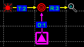
Step 4 View the plots.
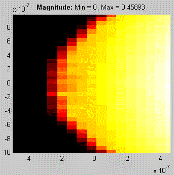
Reflection of Target, No Shift
Reflection of Target, 0.6 micron shift
Reflection of Target, 1.2 micron shift
Reflection of Target, 1.8 micron shift
