MLL Properties Setup Window
The mll Properties Setup Window is used to define important properties about the mll, select the one-dimensional profile used in the calculation, and setup the calculation for the exposure and development of photoresist patterns.
Parameters:
specify important information about the mll.

- Incident index is the index of refraction of the medium directly above the layers.
- Substrate index is the index of refraction of the medium just beyond the layers.
- Number of passes determines how many full cycles of optical propagation the calculation will use to determine the total field irradiance through the layers.
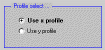
Profile select:
used to determine whether the x profile or the y profile will be used.
The profile is defined as the x axis (y = 0) or the y axis (x = 0) in the current target window. The location of the profile can be changed by moving the window.

Calculation of exposure:
calculate inhibitor concentration data.
Selecting the Perform calculation of exposure check box results in the calculation of the inhibitor concentration through the layers.

- Sub exposure time increment is the time in seconds taken for each subexposure.
- Number of subexposures is the total number of subexposures. The total exposure time is (Number of Exposures) x (Exposure time increment).
- Aerial exposure (mJ/cm2) is the maximum peak exposure level of each subexposure, including the contribution from all source points.
The exposure program used to calculate the inhibitor concentration is selected in the Exposure files window.
If the Begin with previous inhibitor file check box is selected, the inhibitor concentration specified in the Exposure files window will be loaded as the initial distribution before the exposure. If the Begin with previous inhibitor file check box is not selected, the initial inhibitor concentration is uniform throughout the recording layers.
The resulting distribution after exposure is stored in the exposure file.
Calculation of development:
The “Calculation of development” box is used to calculate resist profile data.
Selecting the check box results in the calculation of the resist profile after development. The check box can be selected only if the Calculation of exposure box is selected.

- Parameter vector is a list of parameters that are used by the developer program. An example parameter list for the resim.m program is shown below. The developer program is selected in the Developer Files window.
- Total developer time (sec) is the estimated time used for development. During a development cycle, an incremental calculation of the resist profile is determined. The most accurate results are achieved with short cycles times.
- Number of development cycles is an initial estimate of the number of cycles for the calculation. The program continues to calculate the resist profile changes up to the total developer time or when the maximum number of development cycles is reached. The actual number of development cycles and cycles time can vary due to the autoranging of the program. Usually the cycle time is shortened due to fast development rates, and the number of cycles is increased.
|
Parameter |
Default Value |
Description |
| 1 | 200 | Initial number of sample points evenly spaced across the top surface of the layers being processed in the developer. |
| 2 | 0.25 | Relative distance for the smallest allowed separation of the sample points during development. The distance is relative to the initial separation across the top of the layers. |
| 3 | 2 | Relative distance for the largest allowed separation of the sample points during development. The distance is relative to the initial separation across the top of the layers. |
| 4 | 500 | Maximum number of development cycles. Although the user sets an estimate of the number of cycles in the Number of develop cycles, the resim program can autoscale the time increments if the development is proceeding too rapidly. Therefore, an upper limit is implemented. |
| 5 | 5.63 | Dill’s E1 development parameter. This parameter is specific to each resist. |
| 6 | 7.43 | Dill’s E2 development parameter. This parameter is specific to each resist. |
| 7 | -12.6 | Dill’s E3 development parameter. This parameter is specific to each resist. |
| 8 | 1.75e-6 | Starting depth in the layers for development. This option is used when, for example, liftoff or contrast enhancement layers are used in the exposure but are removed before development. |
| 9 | 2.2e-6 | Maximum depth in the layers through which the resist profile is generated. |

