Development of Heterodyne Interferometer
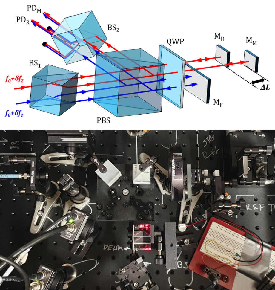
Our research focuses on an optical configuration for a heterodyne interferometer that adopts spatially separate two‑frequency beams to prevent frequency and polarization mixing, thereby eliminating periodic errors. The objective of this work is to design, build and experimentally verify a thermally stable, compact interferometer without periodic error. This system is developed for applications in industry, such as precise measurement of stage motion and machine control, as well as scientific research, including space geodesy. Through our experiments, we have achieved picometer‑level displacement sensitivities in air over frequencies above 100 MHz, verified a higher sensitivity of 3 pm, demonstrated higher thermal stability by a factor of two, and confirmed periodic‑error‑free performance. We have also achieved short‑ and long‑term stabilities of the system during both stationary and dynamic measurements. Building on these results, we are currently working on a single‑block interferometer and a fiber interferometer to further advance the technology.
Laser Stabilization
At LASSO, we work at the limits of optical precision, and one of the key challenges we face is that laser frequency noise is one of the limiting factors to the accuracy of our interferometer readout system. To overcome this, we have implemented several methods to stabilize the frequency of our lasers. The first is the standardized Pound–Drever–Hall (PDH) method, where we use a Zerodur optical cavity as our frequency reference. Building on the PDH approach, two lasers are locked to adjacent modes of the cavity via PDH, and their beat note is measured to create a feedback loop that compensates for cavity fluctuations. In parallel, we operate another system that uses transition lines of specific gas molecules (HCN) as a frequency reference. All these systems are meant to provide stabilized laser sources in designated frequency regimes so that performance of our optical readout system is improved, and they form a core part of our ongoing effort to push the stability and accuracy of LASSO’s interferometric technologies.
Compact Data Acquisition Systems (DAQ)
Accurate, real time DAQs are important for space missions because they communicate important information between spacecraft sensors and scientists on Earth, and these DAQs can be hosted on field programmable gate array (FPGA) development boards.
Our objective is to develop a compact DAQ real time processing system and integrate it with optical components such as interferometers, to program FPGA boards to efficiently extract, filter out interfering signals from space, and optimize raw data from space based laser interferometry experiments and obtain important signal characteristics such as phase shift, which can represent satellite separation distance, as an example.
Further, we are planning to program FPGA boards to implement oscilloscopes and phase meters, and to control and drive optical laser sources in parallel. We also aim to emulate GRACE FO’s DAQs within the laboratory for future space missions such as the Laser Interferometer Space Antenna (LISA), which will ultimately optimize payload for future GRACE FO like missions. We use programming languages such as Vivado, VHDL, Verilog, C, Python etc.
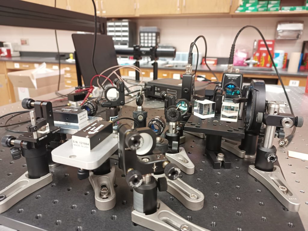
Heterodyne Interferometer
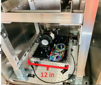
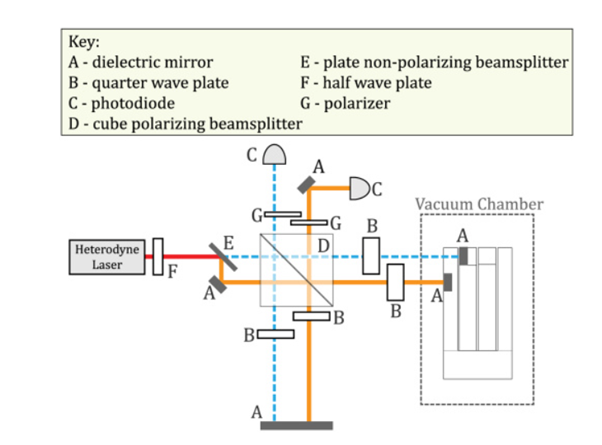
By using a heterodyne interferometer, resonator test mass displacement is measured optically. We integrate the resonator, the heterodyne interferometer, and the laser to measure parameters such as Quality factor (Q‑factor), minimum displacement, acceleration sensitivity, Q‑factor, and noise floor level. We also test them further in vacuum to predict the performance in space, and one such setup is shown in the figure beside. In our lab, we have set up a little test bench consisting of a vacuum chamber and a suspended platform where we basically mount our mechanical resonator. The suspended platform is just to help us isolate external noises, and the schematic of the testing is shown in the figure beside.
Fabry-Perot Cavity
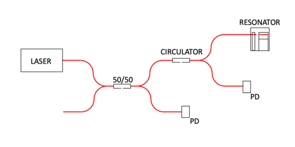
Using a Fabry–Perot cavity, the cavity is formed between the input fiber and a fiber placed on the test mass, and the fiber tips act as the mirrors. As the test mass moves, the cavity length changes. Light is transmitted when it is on resonance with the cavity, and this resonance condition is met when the round‑trip cavity length is an integer m number of wavelengths. Laser light is input through the circuit, a 50/50 fiber coupler allows for power normalization, and an optical circulator is used to measure the reflected light from the cavity. Since light transmits when on resonance, resonance peaks occur at the minimum. Since cavity resonance is proportional to the length of the cavity, any changes in cavity length will result in a change in reflected power. Oscillations of the test mass will show up as oscillations in the voltage readout, and we measure the fluctuations of this voltage using equations. From this voltage fluctuation, we measure the displacement and ultimately acceleration. After we get the desired results in the room conditions, we test the resonator in the vacuum to minimize the environmental noise levels.