
Testing
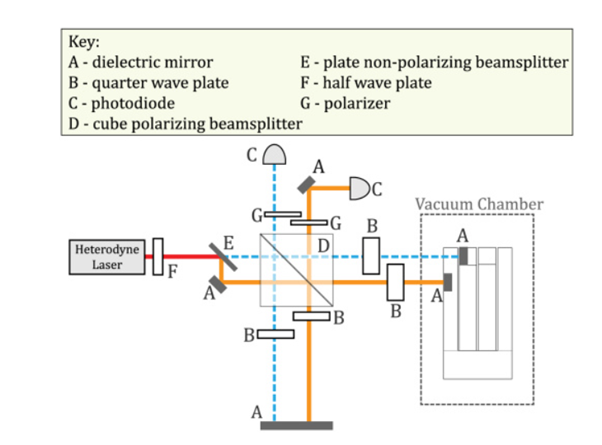
1. Using Heterodyne Interferometer
- Resonator test mass displacement is measured optically.
- We integrate resonator, heterodyne interferometer and LASER to measure the parameters such as Quality factor (Q-factor), minimum displacement, acceleration sensitivity, Q-factor and noise floor level.
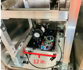
- We also test them further in vacuum to predict the performance in space. One such set up is shown in the figure besides.
- So right now, in our lab, we have set up a little test bench consisting of a vacuum chamber, a suspended platform , where we basically mount our mechanical resonator.
- The suspended platform is just to help us isolate external noises. The schematic of the testing is shown in the figure besides.
2. Using Fabry-Perot cavity
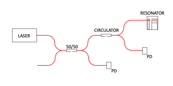
- The cavity is formed between the input fiber and a fiber placed on the test mass. The fiber tips act as the mirrors. As the test mass moves, the cavity length changes.
- Light is transmitted when it is on resonance with the cavity. This resonance condition is met when the round-trip cavity length is an integer m number of wavelengths,

- Laser light is input through the circuit. A 50/50 fiber coupler allows for power normalization, and an optical circulator is used to measure the reflected light from the cavity. Since light transmits when on resonance, resonance peaks occur at the minimum.
- Since cavity resonance is proportional to the length of the cavity, any changes in cavity length will result in a change in reflected power.
- Oscillations of the test mass will show up as oscillations in the voltage readout. We measure the fluctuations of this voltage using equations. From this, voltage fluctuation, we measure the displacement and ultimately acceleration.
- Future: After we get the desired results in the room conditions, we test the resonator in the vacuum to minimize the environmental noise levels.