
Gravitational Wave Detection
OPTICAL TRUSS INTERFEROMETER
What is LISA?
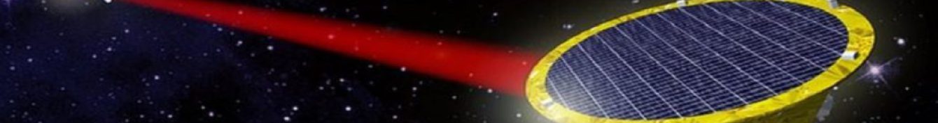
- The Laser Interferometer Space Antenna (LISA) is a mission led by ESA, in collaboration with NASA and an international consortium of scientists, to create a large-scale space-based gravitational wave observatory.
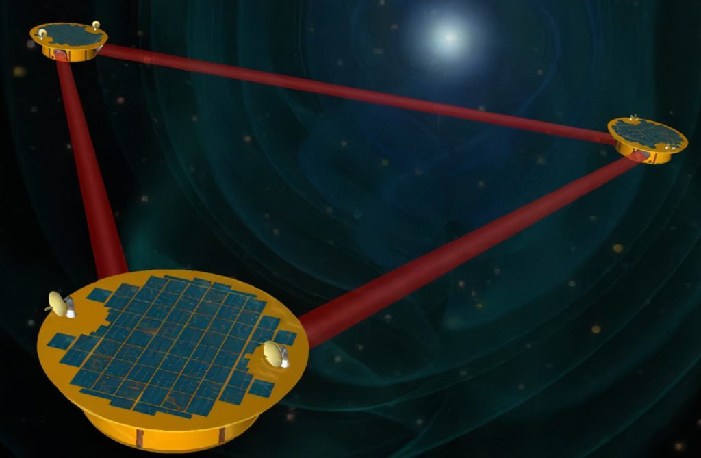
- The observatory will consist of a constellation of three spacecraft, each separated by 2.5 million kilometers to form an equilateral triangle in their formation.
- One of the main technological goals for LISA is to measure variations in the separation between free falling test masses aboard each spacecraft with a sensitivity of 10 pm/√Hz using interferometric methods.
- The LISA telescopes will relay the laser beams, to and from each spacecraft, that are used to measure the separation between freely falling test masses which are shielded, but untouched by the spacecraft. An incoming gravitational wave will induce perturbations in the separation between each pair of test masses, and these perturbations can then be measured and analyzed to determine the source and origin of the wave.
- A key difference between LISA and ground-based detectors is the ability to measure gravitational waves in a bandwidth from 0.1 mHz to 1 Hz. Detection in this bandwidth has not yet been achieved in gravitational waves and would introduce valuable information about gravitational wave sources and fundamental physics.
Our work:
- One of the most critical components to LISA are the six telescopes (two per spacecraft) that will be used to relay the laser beams. Extensive design work and testing must be done on these telescopes before they can be used in LISA.
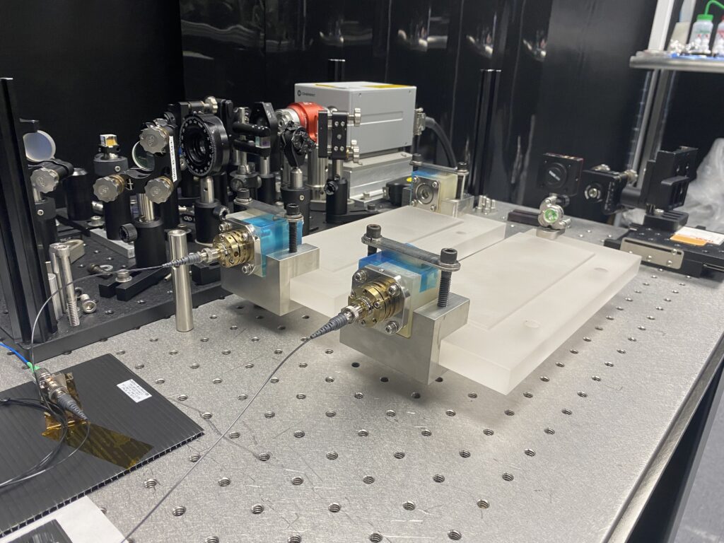
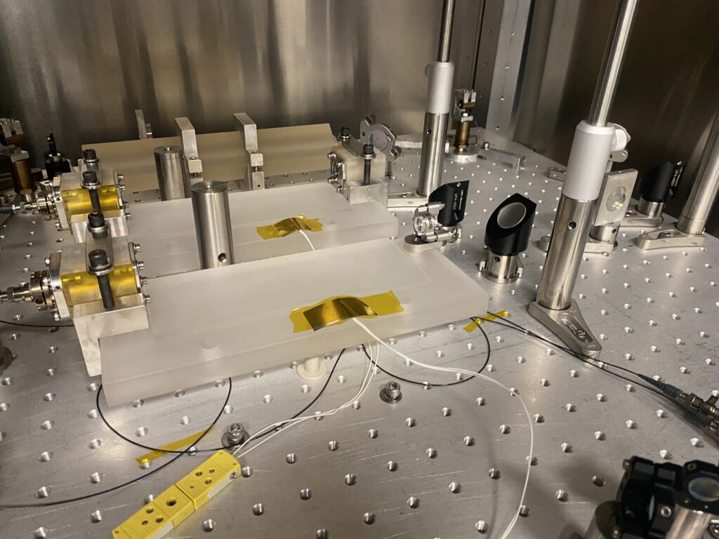
- One proposed way to monitor the dimensional stability of the LISA telescopes is to use a Fabry-Perot based optical truss interferometer (OTI).
- The OTI system will be composed of three Fabry-Perot cavities, each mounted lengthwise at different positions around the telescope. Variations in the cavity lengths will in principle be due to variations in the telescope length along the three different lateral positions.
- Members of the LASSO team are working to develop a compact fiber-based PDH system that integrates a fiber-coupler, mode matching optics, and a cavity input mirror into a compact input stage for each cavity. These input stages will be attached around the primary mirror of the telescope, while the rear cavity mirrors will be attached around the secondary mirror of the telescope.
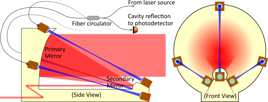
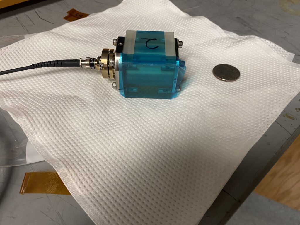
- Using a Pound-Drever-Hall (PDH) frequency locking technique, variations in the cavity lengths will change the frequency of the locked laser light. Thus, monitoring the frequency variations in the laser light will in effect monitor length variations in the telescope structure. The frequency variations will be monitored using heterodyne detection by measuring a beat frequency between the laser light from each cavity and a laser that is locked to a stable reference cavity. We have designed and developed first generation OTI prototype cavities, and our current work involves testing the stability performance of these units when mounted onto ultra low expansion (ULE) glass plates and tested with various PDH-based frequency stabilization methods.
Researchers Involved:
COMPACT SENSORS FOR LIGO
- Gravimetry is vital for operations in the Laser Interferometer Gravitational-wave Observatory (LIGO) project.
- In order to detect gravitational waves, LIGO’s interferometers must be able to track the position of a test mass with an accuracy on the order of 10-19 m. However, vibrations coming from outside the interferometer, such as seismic activity and cars driving along the road, will make noise so the LIGO interferometers will not reach this displacement sensitivity.
- With the use of gravimeters, these outside vibrations can be detected and removed from the LIGO systems via active feedback, allowing LIGO researchers to achieve the desired displacement sensitivity.
- The gravimeters employed by LIGO tend to suffer from one or more drawbacks, including being large, expensive, and incompatible with vacuum or cryogenic temperatures.
- Our Work: LASSO is trying to develop a gravimeter that does not have these drawbacks while maintaining a competitive acceleration sensitivity.
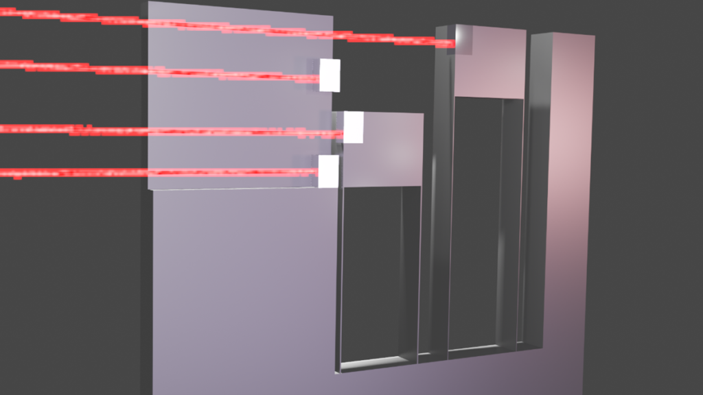
- As shown in Figure, the sensor we envision creating for use in LIGO uses two optomechanical resonators with different frequencies. Such resonators are projected to have acceleration noise floors that are competitive with the accelerometers already used by LIGO and using two different resonators increases the bandwidth of the sensor to meet LIGO’s requirements.