
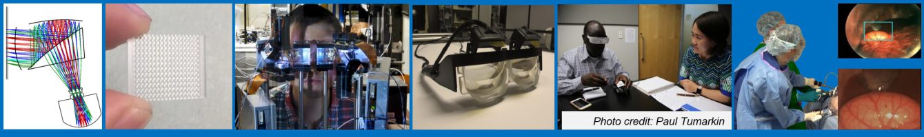
Polarized Head Mounted Projection Display (p-HMPD)
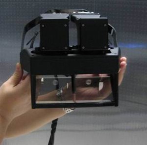
In existing optical see-through head-mounted displays (HMD), it is a common challenge that the displayed image lacks brightness and contrast compared to the direct view of a real-world scene. Consequently, such displays are usually used under dimmed indoor lighting conditions, excluding the feasibility of applying such information displays outdoor or in scenarios where well-lit environments such as in an operation room are demanded. The lack of image brightness is further aggravated in the design of a see-through head-mounted projection display (HMPD) due to the multi-pass beam splitting scheme and low retro-reflection efficiency. The existing designs of HMPDs typically leads to an overall light efficiency below 10%. We propose a simple but elegant design of a polarized head-mounted projection display (p-HMPD). By managing the polarization property in the optical system, the proposed p-HMPD design can greatly improve the image brightness (by about four times), contrast, and color vividness of a conventional HMPD system. This makes it possible to use the p-HMPD system in a well-lit indoor environment. The first prototype showed on the left was a VGA-resolution design with 55-degrees of diagonal field of view. We recently completed the a prototype based on a pair of XGA-resolution FLCOS microdisplays. The prototype was shown on the left as well.
Schematic Design
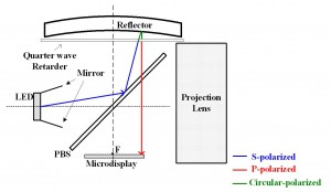
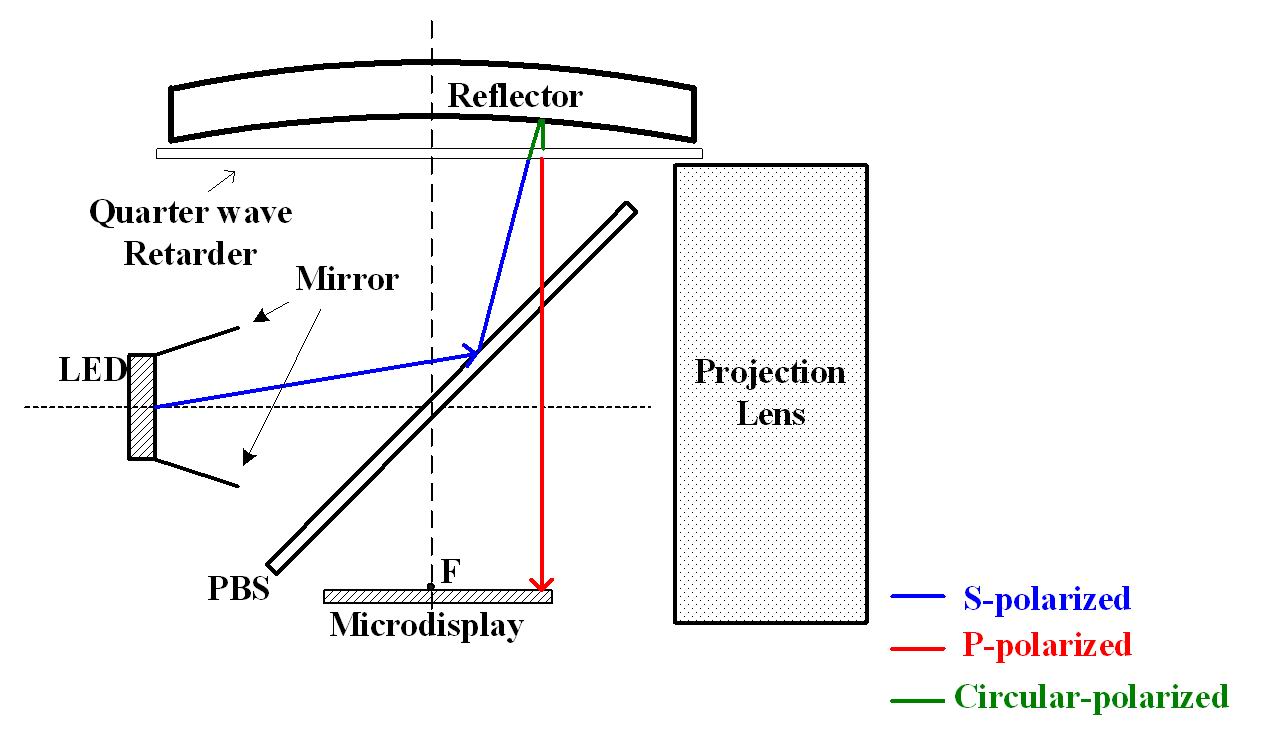
To address this illumination problem, a polarized head-mounted projection display (p-HMPD) was proposed and a prototype based on a pair of transmissive AMLCDs was designed recently. By carefully manipulating the polarization states of the light propagating through the system, a p-HMPD can potentially be three times brighter than a traditional non-polarized HMPD design using the same microdisplay technologies. A schematic design of a monocular p-HMPD configuration is illustrated in Fig.1. The image on the LCD display is projected through the projection lens, forming a real intermediate image. The light from the LCD is manipulated to be S-polarized so that its polarization direction is matched with the high-reflection axis of the polarized beamsplitter (PBS). After the projected light is reflected by the PBS, it is retro-reflected back to the same PBS by a retro-reflective screen. The depolarization effect by the retro-reflective screen is less than 10% within ±20 degrees and is less than 20% up to ±30 degrees. As a result, the retro-reflected light remains dominantly the same polarization as its incidence light. In order to achieve high transmission through the PBS after the light is retroreflected back, a quarter-wave retarder is placed between the PBS and the retro-reflective screen. By passing through the quarter wave retarder twice, the incident S-polarized light is converted to P-polarization and transmits through the PBS with high efficiency. Thus the projected image from the microdisplay can be then observed at the exit pupil of the system where the eye is placed.
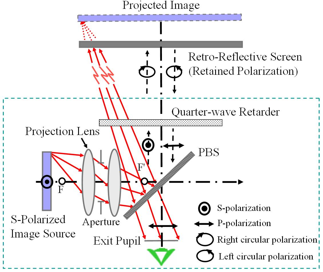
Fig 1 Schematic design of p-HMPD
System Design
We select the SXGA-R2D ferroelectric Liquid-crystal-on-Silicon (FLCOS) microdisplay kit by Forth Dimensional Displays Limited as the image source due to its high resolution, optical efficiency and compactness. A 0.5″ Alphalight® color LED illuminator by Teledyne Inc. is selected as the light source for the FLCOS microdisplay which is operated in the reflective mode. The core parts design of the p-HMPD includes the design of the light engine and the projective lens.
Design of Light Engine
Since FLCOS display is operated in reflective mode, a light illumination unit called light engine is design for the display. The schematic design of the light engine is shown in Fig 2(a). To increase the light efficiency of the light engine, the polarization of the light is well managed to achieve highest light efficiency. As shown in Fig. 2(b), a mirror based light pipe is deigned for the LED panel in order to increase the light efficiency and the uniformity of the display panel.
-
- Fig 2 (a). Design of the light engine.
-
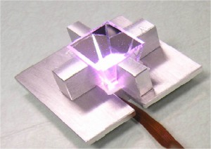
- Fig 2 (b). Photos of LED panel with tapered light pipe.

Design of Compact Projection lens
A projection lens is designed based on the light engine of the microdisplay. This system is all-plastic system and a diffractive optical element is used to correct chromatic aberrations. Table 1 shows the layout of the design. Fig 3 shows the picture of the lens.
| Table 1 – Specification of the projection lens | |
|---|---|
| Parameter | Specification |
| Projection lens | |
| Effective focal length | 21.6 mm |
| Overall length | 34 mm |
| Entrance pupil | 10 mm |
| Image mode | Image space telecentric |
| BFL | 30.5 mm |
| FOV | 55° |
| Wavelength range | 486—656 nm |
| Distortion | <4% over FOV |
| Weight | <9 grams |